This section is under redevelopment and will reappear soon.
We apologise for any inconvenience.
This section is under redevelopment and will reappear soon.
We apologise for any inconvenience.
Please take a few minutes to read our Legal notice & disclaimer,
Privacy Policy and
Copyright statement |
![]()
OzCoasts is undergoing a redevelopment.
We have already upgraded the design of the site and we will be working to update the content over the coming months. Unfortunately many pages may not be where they used to be because this is such a major upgrade. If you can’t find something, please use the search box or feel free to contact us.
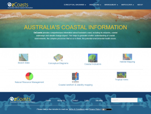
If you can’t find what you are looking for, try searching for content below.